
Search Results for 85
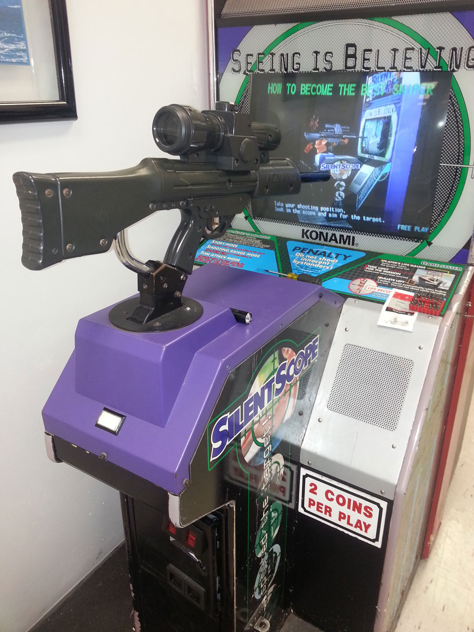
Shall we play a game?
Been playing out with the camera on my new phone (Samsung Galaxy Note 2 – sweetness) at the arcade, amazing how far cell phone cameras have come…

Modifying Pinball GI Circuits for DC Part 1: WPC95 Theory
/EDIT: UPDATE: This did not really work out as planned, need to look at the data on the scope and see exactly what is happening with these SCR’s…
So the theory was incorrect :sadface:
I am going to do a series of articles on modifying Pinball GI circuits for DC (to run LEDs instead of incandesant lamps) in order to get rid of annoying 60hz strobing/flicker.
Part 1: Williams WPC95
The Williams WPC95 was the last of William’s pinball machines board systems (before Pinball 2000). The board used 3 TRIACs to control 3 GI circuits each capable of driving 18 lamps and 2 “always on” circuits generally used for the backbox (boring! more on that later).

Ok so here is a quick GI block diagram/theory of operation from a WPC95 game manual. Data from the CPU board comes in via J102, selects a 74LS374, which drives a MPSD52 (2N5401) which then drives a TRIAC that lets the AC flow from J103 (6.3VAC secondary from power transformer) to J105 which goes to the controlled GI lamps.

(Click for larger version)
Here is the actual relevant part of the WPC95 schematic (from the WPC95 manual). You can see the three data lines coming from U2 (74LS374), driving the three MPSD52 (2N5401) and then driving the three TRIACs. TRIACs are pretty neat devices, basically like a transistor but for AC instead of DC (see: https://en.wikipedia.org/wiki/TRIAC), but since we want to use DC for our GI LEDs they need to go. If you notice the general layout of this circuit is very similar to other repeating circuts on the Power Driver board including the solenoid and general purpose driver outputs, so we are basically just going to copy those and insert them in place of the original TRIAC based one.
Doing that gives us this

(Click for larger version)
Ok so here we have replaced the TRIAC (Q3, Q4, Q5) with TIP102s (for the sake of keeping things the same) one important thing to note immediately is that the TIP102 does *NOT* have the same pinout as the BT138E TRIACs we are removing, so the easiest way to deal with that is simply mount the transistor onto the heatsink upside down, and solder some bits of wires to the leads and then run those leads to the pads on the board in the correct order. You also need to add a 2.7K resistor between the Base and Emitter of the TIP102 as indicated in the schematic, you can just attach the resistor straight to the transistor between pins 1 and 3.
Additionally the following needs to be done to the board:
The 560 ohm resistors at R24/R18/R21 need to be replaced with 470 ohm resistors
The 51 ohm resistor at R26/R20/R23 need to be replaced with 68 ohm resistors AND a 1N4004. Simply attach both devices to each other in a V shape and then insert in place of R26/R20/R23
Additionally (and not pictured in the schematic) you can add some large capacitors on the output of the TIP102s to try and smooth out the PWM that Williams machines use to “dim” the GI circuits, with LEDs you just get a really noticeable strobing instead of the desired dimming, but adding a large cap should “smooth out” the PWM enough to at least suppress the strobing to tolerable levels.
Finally and a very important note, you can NOT put AC straight into this circuit, it either requires separate rectification/filtering/regulation of the GI secondary coming from the main power transformer, or a small DC switching supply which is what I generally use. Small 5v switchers are readily available and provide a “5v” adjust which usually gives you a little play in the output voltage, allowing you to dim or brighten the GI LEDs as desired.
Pictures of the actual modifications coming soon!
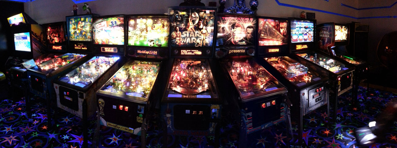
Arcade Odyssey Tournament photos
Uploaded the photos from the tournament 2/4/2012 onto my Flickr account…
2012-02 Arcade Odyssey Tournament
Some of my favorites:


And finally, not to show off or anything 😉

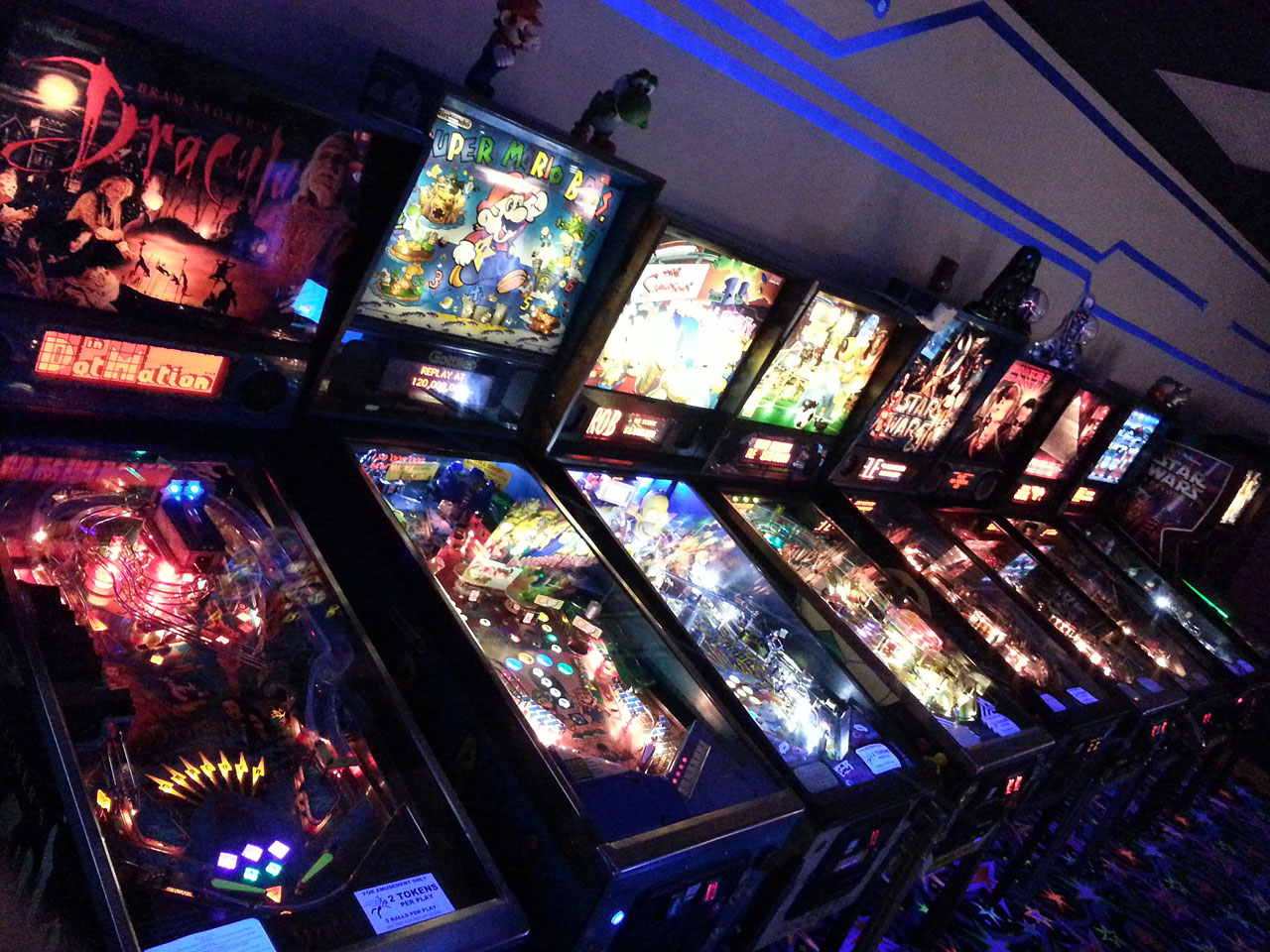
The wall is full
Well, the wall is officially full

The wall of Pins
My roommate picked up the Ripley’s Believe it or Not!, I picked up the South Park and “Bram Stoker’s Dracula”
Both the South Park and Dracula will need quite a bit of work, the South Park seems to have come from the now defunct Game Works (now Game Time) and I picked up the Dracula from a guy that has been fixing Arcade/Pin’s for a long time…
The South Park works fine, but has some pretty extreme playfield wear, the ball drop from the right wire ramp is pretty extreme, wearing down into the wood. Besides that its actually pretty ok, just needs some cleaning, a new Kenny and some new plastics. Unfortunately the plastics are kind of pricey so its going to have to wait a bit…
The Dracula needed repair on the CPU board, audio board, DMD board, AND the power/driver board (aka ALL of them). But after some time with the soldering iron and my trusty Fluke 73 its come back from the dead (har har)… Playfield needs some cleaning, currently have it stripped down, cleaned, polished and waxed, just waiting some replacement bits before applying a new mylar sheet and reassembling the playfield. After that I am probably going to sell it, I bought it because it was a good deal, and while its actually a pretty great pinball I’d rather have the space open for a machine on my wish list 🙂
Aaaaand another…
So after getting the StarWars pinball machine the next one I kept a lookout for was a GoldenEye pinball machine, and wouldn’t you know it one appeared on Craig’s List. Called up the owner and he brought it over, said it belong to a friend of his that purchased it for his son and it never got played. And it looks it, except its got quite a layer of dust/suit(?) on it. So I am guessing it spent some time in a garage.

The Pin’s
So pretty much everything works on it, a few bulbs out and the satellite motor is a dead short, but the magnets and everything else works. So ordered some spare parts and a LED kit to retrofit it.
Started breaking it down so I can clean the playfield and all the plastics/parts etc.

Cleaning the playfield
Here are the ramps removed, going to try and clean them up/polish and clear up the plastic using Novus.

Right & Center Ramps

Left Ramp
Much work to do!